The Yamaha Tracer 9 GT+ brings advanced rider aids into sport-touring, and that makes maintenance more technical than a typical chain-drive motorcycle. Radar cruise sensors, cornering electronics, ride-by-wire throttle control, and networked control units all depend on correct inspection methods. On this model, a small issue such as a weak battery, a contaminated front radar cover, or improper fastener handling can trigger warnings that riders mistake for sensor failure. I have seen owners replace parts too early when the real problem was alignment, connector tension, or a service step skipped after bodywork removal. Diagnosing the radar-cruise system correctly starts with understanding the machine as a metric Japanese platform, not just as a motorcycle with electronics.
This matters because the Tracer 9 GT+ sits at the intersection of three service cultures: Japanese Industrial Standard hardware practice, modern electronically controlled transmissions and driveline logic often discussed alongside dual-clutch maintenance principles, and the everyday metric quirks that shape torque, thread pitch, tool fit, and electrical testing. In practical terms, technicians need to know why a JIS crosshead matters, how battery voltage stability affects control modules, why calibration procedures must follow exact load and ride-height conditions, and how metric fastener substitutions can create hidden faults. This hub explains those links clearly so riders and workshop staff can diagnose radar-cruise sensor concerns with fewer wrong turns, lower parts cost, and better confidence in the repair.
Understanding the Tracer 9 GT+ radar-cruise architecture
Yamaha’s Tracer 9 GT+ uses forward-facing radar to support adaptive cruise control, along with linked braking and rider-assist functions coordinated through multiple electronic control units. The radar module itself does not work in isolation. It exchanges data with the engine control unit, inertial measurement unit, ABS modulator, throttle actuator logic, wheel-speed sensors, and dashboard gateway over the bike’s communication network. That means a radar warning can originate from several layers: the sensor, the mounting angle, the power supply, the network, or another subsystem feeding implausible data.
When riders ask what symptoms point to radar-cruise trouble, the answer is usually one of four categories. First, the cruise function may refuse to engage. Second, it may engage but immediately cancel. Third, following-distance behavior may become inconsistent. Fourth, a warning message or fault code may appear after unrelated maintenance, especially after front fairing, mirror, screen, battery, or fork work. I have repeatedly found that post-service faults are more common than true radar hardware failure. Body panels can be reinstalled with slight stress on the harness, the radar bracket can be bumped during accessory fitting, and battery disconnection can expose a marginal charging system that had gone unnoticed.
Environmental contamination is another common factor. Road film, insect residue, wax buildup, or a cracked radar cover can distort the sensor’s view. Unlike simple headlight lenses, radar covers must remain dimensionally stable and free from metallic paint contamination or heavy aftermarket films. Even a decorative sticker can alter performance. The first diagnostic step is therefore basic but essential: inspect the cover, mounting, connector seating, fuse condition, and battery state before assuming the module is defective.
The JIS standard and why it affects sensor diagnosis
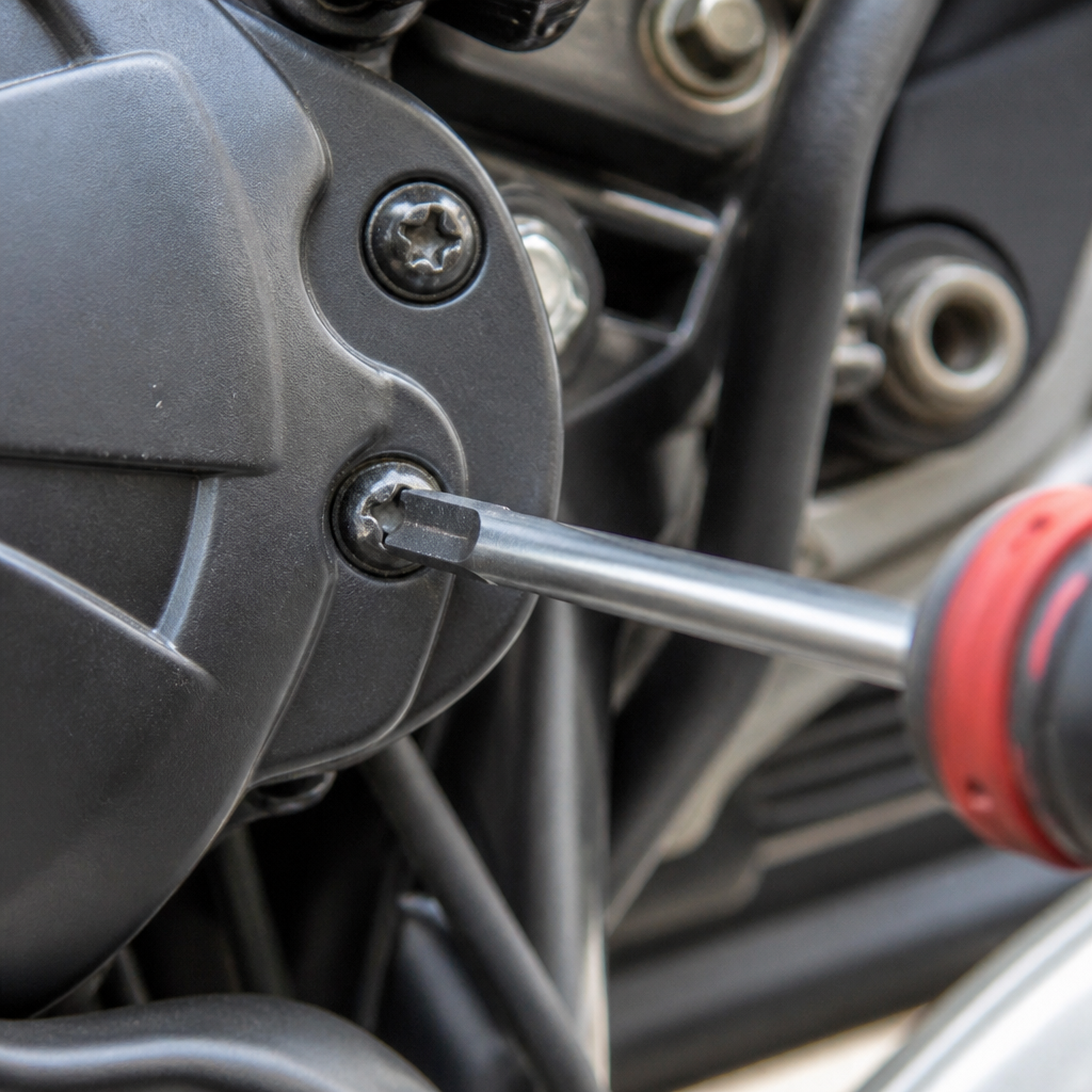
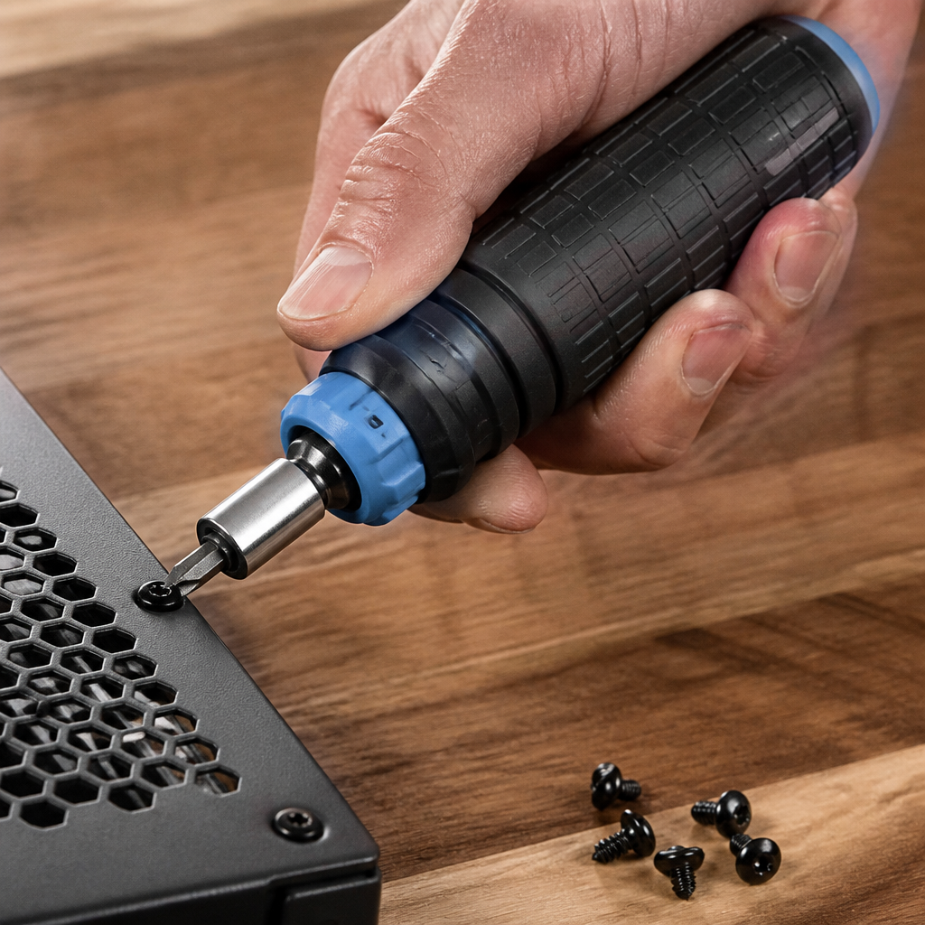
Japanese motorcycles still punish sloppy tool selection. Many owners call every crosshead screw “Phillips,” then strip bodywork screws, reservoir covers, and sensor-adjacent fasteners with the wrong driver. JIS crosshead recesses are designed differently from Phillips, with less intentional cam-out. On Yamaha service points, using a proper JIS driver or high-quality bits such as Vessel, Hozan, or JIS-spec impact bits reduces slip, preserves torque transfer, and prevents damage that later complicates panel removal and refit. That matters directly when accessing the Tracer 9 GT+ front bodywork around the radar module.
A rounded screw head is not just an annoyance. It encourages prying, panel flex, and rushed disassembly, any of which can alter bracket position or stress the radar harness. I have seen technicians distort mounting tabs because one seized crosshead forced side-loading during removal. After reassembly, the bike showed intermittent cruise cancellation at highway speed. The sensor itself was fine; the bracket sat a fraction out of specification. JIS awareness prevented that on the next repair because all related fasteners were removed cleanly, torqued correctly, and the bracket stayed neutral.
JIS thinking also applies to electrical connectors and hardware discipline. Japanese service manuals assume methodical cleaning, thread preservation, and correct torque on relatively small metric fasteners. Over-tightening an M5 or M6 fairing support bolt can shift a mount or crack a plastic boss. Under-tightening can allow vibration that changes radar aim over time. Use a calibrated 1/4-inch torque wrench for low values, not guesswork. If threadlocker is specified, use the stated strength; high-strength compound on serviceable hardware creates unnecessary extraction risk later. Precision in these small tasks is what keeps advanced rider-assistance systems functioning properly.
DCT maintenance principles and what they teach Tracer owners
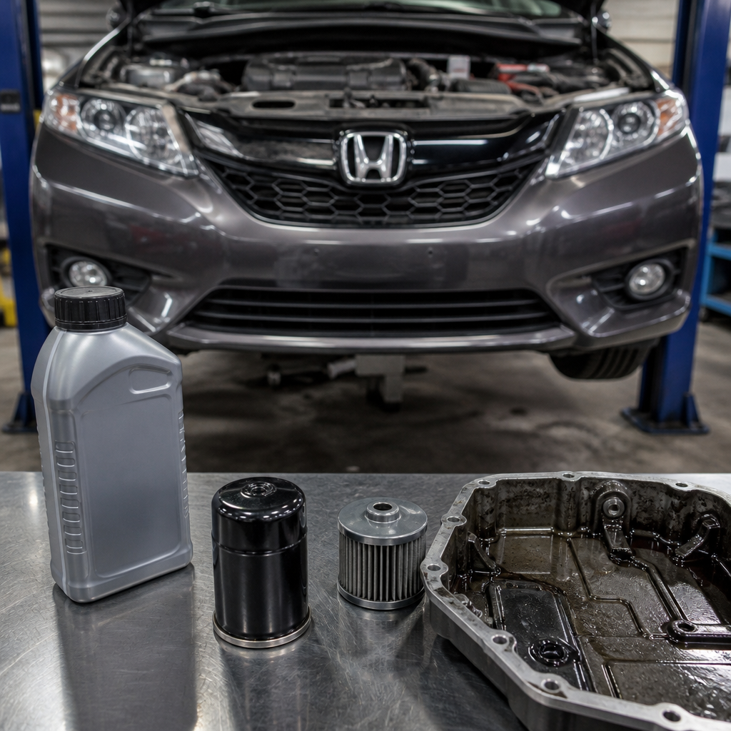
The Tracer 9 GT+ does not use a dual-clutch transmission, but DCT maintenance principles still offer a useful framework for diagnosing electronically managed motorcycles. On DCT-equipped bikes from Honda, smooth operation depends on fluid quality, battery health, shift actuator calibration, sensor plausibility, and exact adherence to service procedures. The lesson carries over directly: when a machine blends mechanical systems with control software, small foundational faults create large electronic symptoms. A weak battery does not just crank slowly; it can drop module voltage during self-checks and generate misleading communication or sensor codes.
In workshop practice, that means every radar-cruise diagnosis should begin with baseline health checks similar to the way a careful technician approaches DCT complaints. Confirm battery resting voltage, charging voltage under load, and ground integrity. Verify wheel sizes, tire wear consistency, and tire pressures, because wheel-speed interpretation and pitch attitude calculations depend on stable rolling inputs. Check brake switch function and throttle return because adaptive cruise logic monitors both. Review recent maintenance history: chain adjustment, fork service, steering-head work, accessory wiring, and software campaigns are all relevant.
Another DCT-related lesson is that calibration and learned values matter. Riders often assume disconnecting the battery simply resets the clock, but on modern motorcycles it can also reveal pending adaptations or stored faults that need proper scan-tool review. If the Tracer has had suspension changes, ride-height alterations, or front-end impact, sensor alignment should be treated as a measured procedure, not a visual guess. That same disciplined mindset used on DCT clutch relearn processes belongs here too. Follow the service manual sequence exactly, because electronic systems are unforgiving of shortcuts.
Metric quirks that commonly cause false radar faults
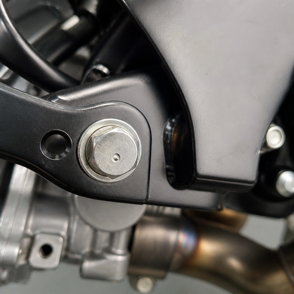
Metric motorcycles seem straightforward until mixed hardware, accessory kits, and nonstandard workshop habits introduce problems. The Tracer 9 GT+ is full of fine-thread and small-diameter fasteners where thread pitch, shoulder length, and washer stack-up matter. Swap an M6 flange bolt for a generic hardware-store replacement that is a few millimeters longer and it may bottom out before clamping the bracket. The assembly feels tight, yet the radar mount can vibrate. Use an incorrect washer with too large an outer diameter and it can preload a plastic mounting ear unevenly.
Electrical diagnosis has metric quirks too. Battery terminals on Japanese bikes are compact, and accessory pigtails often stack poorly under the terminal screw. That can create intermittent voltage drop during bumps, exactly the kind of event that cancels adaptive cruise. Ground points may look clean while hiding paint, oxidation, or slight loosening. Harness routing near the steering head is another recurring issue. If a GPS lead, heated-gear harness, or phone charger presses against the factory loom, repeated full-lock movement can fatigue wires or partially unseat a connector over time.
Suspension setup is often overlooked. Changing preload affects ride height and pitch, which influences the physical orientation of a forward radar unit. Yamaha designs within a tolerance range, but extreme sag errors, overloaded luggage, or aftermarket lowering links can push geometry far enough to matter. In real use, I have seen heavily loaded touring setups trigger inconsistent cruise behavior because rear sag was excessive and the front radar angle was no longer ideal. Correcting sag did more than improve handling; it restored reliable system behavior without replacing any electronics.
| Check area | Typical mistake | Likely symptom | Best practice |
|---|---|---|---|
| Radar cover | Wax, film, crack, sticker | Warning or poor target detection | Clean with approved plastic-safe products; inspect for damage |
| Fasteners | Wrong JIS tool or incorrect metric replacement bolt | Misalignment after service | Use JIS drivers and match bolt length, pitch, and flange type |
| Battery and grounds | Low voltage or loose accessory stack | Cruise will not engage or cancels | Load-test battery and secure terminals correctly |
| Harness routing | Pinched loom near steering head | Intermittent faults during turns or bumps | Inspect full-lock movement and restore factory routing |
| Suspension geometry | Excessive sag or lowering link | Inconsistent operation at speed | Set sag to specification before calibration checks |
A practical diagnostic workflow for radar-cruise sensor issues
The fastest path to an accurate repair is a structured workflow. Start with the complaint: when does the fault occur, at what speed, in what weather, and after what recent work? Then perform a visual inspection of the radar cover, bracket, front fairing mounts, and harness connectors. Next, verify battery and charging condition with a digital multimeter and, ideally, a conductance or load tester. Pull fault codes with a Yamaha-compatible scan tool if available, because current and history codes help separate hard failures from transient low-voltage events.
After electrical basics, inspect mechanical alignment. Look for uneven panel gaps, witness marks around bracket fasteners, bent stays, and signs of minor impact such as a dropped bike or parking-lot bump. Confirm tire sizes and wear pattern, because unusual front-to-rear diameter relationships can influence system plausibility checks. Check wheel-speed sensor cleanliness and air gap where specified. On any bike fitted with auxiliary lights, alarm systems, radar detectors, or USB modules, inspect for electromagnetic noise sources and poor-quality power taps. Accessories do not always cause faults, but they raise the odds.
Road testing should be controlled and repeatable. Test on a clear multilane road with stable lane markings and moderate traffic, not in dense urban conditions where target acquisition is naturally inconsistent. Try each following-distance setting. Note whether standard cruise works differently from adaptive cruise. If the issue appears only over bumps, think wiring or terminal tension. If it appears after rain or washing, suspect connector sealing, cover contamination, or water ingress. If it appears only with luggage and a passenger, measure sag and inspect rear preload settings before condemning the radar unit.
When replacement is truly necessary, use OEM parts and follow any aiming or initialization procedure exactly. Advanced rider-assistance components are not ideal places to save money with unknown used parts. Salvage modules may carry hidden impact history or incompatible software revisions. Finish with a documented test ride and a record of voltages, torque values, and code status. That documentation protects both the rider and the technician.
Building a maintenance encyclopedia around JIS, DCT logic, and metric practice
As a hub topic, this subject works best when riders treat it as an organized maintenance encyclopedia rather than a single fault guide. One branch should cover JIS standards in depth: screw geometry, proper driver selection, impact-driver use on seized fasteners, and common Yamaha bodywork mistakes. A second branch should cover DCT maintenance concepts as transferable diagnostic discipline: battery stability, adaptation logic, actuator dependency, fluid and friction effects, and why electronic complaints often begin with basic service health. A third branch should catalog metric quirks: thread pitches, low-range torque control, flange hardware identification, sag measurement, and connector care on Japanese motorcycles.
For Tracer 9 GT+ owners, the benefit of this encyclopedia approach is speed and accuracy. Instead of searching random forum posts, they can move from a radar warning to the exact supporting topic they need: battery diagnostics, front-end disassembly, fairing fastener identification, or suspension setup. That structure also improves workshop communication. A rider can say the issue started after windscreen bracket installation, the battery tested at a certain voltage, sag is outside target, and the radar cover has no damage. Those are useful facts, not guesses, and they lead to faster repairs.
The key takeaway is simple: diagnosing the Yamaha Tracer 9 GT+ radar-cruise sensors is rarely about the sensor alone. It is about disciplined metric service, correct JIS tool use, and the same systems-thinking that modern electronically managed motorcycles demand. Start with the basics, measure before replacing, and respect geometry, voltage, and fastener integrity. Build your maintenance process around those principles and the radar-cruise system becomes far less mysterious. If you maintain or tour on a Tracer 9 GT+, use this hub as your starting point, then create a checklist for your own bike before the next service interval or warning light appears.
Frequently Asked Questions
What are the most common causes of radar-cruise warnings on a Yamaha Tracer 9 GT+?
On the Tracer 9 GT+, a radar-cruise warning does not automatically mean the radar unit itself has failed. In real-world maintenance, the most common causes are far less dramatic: a weak or unstable battery, low system voltage during startup, contamination on the front radar cover, recent bodywork removal or impact damage, poor electrical connections, or fault codes stored after another related system event. Because the bike uses networked control modules, the radar sensor is part of a larger electronic chain that includes power supply quality, CAN communication, braking inputs, throttle control, and other rider-aid systems. If one link in that chain behaves outside expected parameters, the rider may see a warning that appears to point at the radar system even when the root cause is elsewhere.
Dirt, bug residue, road film, wax buildup, and even a partially obstructed radar cover can interfere with radar performance enough to disable cruise-related functions. Voltage issues are also extremely common on modern motorcycles with advanced electronics. A battery that still starts the engine can nonetheless dip low enough during cranking to trigger electronic warnings or irregular module behavior. In addition, if fairings, brackets, or front-end components have been removed and reinstalled improperly, sensor alignment or mounting stress can become a factor. Before assuming expensive component failure, it is smarter to begin with a complete visual inspection, battery and charging-system testing, connector checks, and code scanning. On this model, the basic causes are often the ones that get overlooked first.
How should I inspect and clean the radar sensor area without creating new problems?
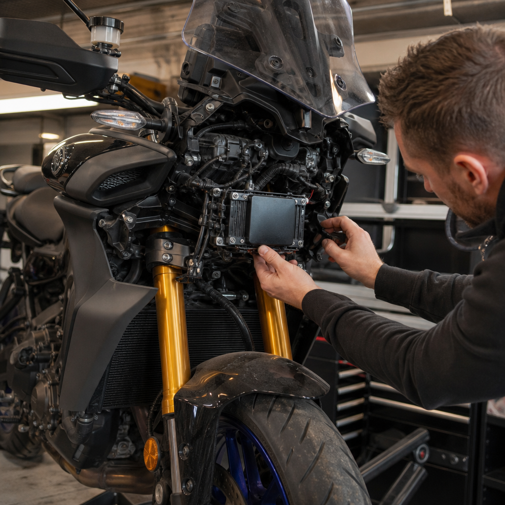
The safest approach is to treat the radar area as a precision electronic component, not just another piece of plastic bodywork. Start with the motorcycle switched off and stable on a secure stand. Inspect the radar cover and surrounding mounting area in good light. Look for bug splatter, tar, heavy dust, dried water spotting, wax residue, minor impact marks, cracked trim, loose fasteners, or evidence that the front bodywork has shifted. Even subtle misfit in the surrounding panel can matter if it changes the radar’s physical orientation or creates vibration. Also check for accessory items such as added lights, brackets, decals, or film that may partially interfere with the sensor’s operating path.
When cleaning, use only mild soap and water with a soft microfiber cloth. Avoid abrasive pads, harsh solvents, petroleum-based cleaners, aggressive bug removers, or polishing compounds unless Yamaha specifically approves them for that surface. Do not press hard on the radar cover and do not pry or flex the panel to “check” for looseness. If the area needs deeper cleaning, rinse first to float away grit, then wipe gently. Afterward, dry the surface fully and inspect again. If body panels or the sensor mounting hardware must be removed, follow the service procedure exactly and use the correct fastener sequence and torque values. Overtightening or uneven fastening can place stress on the mount, and that can lead to alignment issues or false assumptions about sensor failure. The goal is not just a clean sensor face, but a clean, undisturbed, correctly mounted sensor assembly.
Can a weak battery or charging-system issue really affect the radar-cruise system?
Yes, absolutely. On the Tracer 9 GT+, the radar-cruise system relies on stable voltage and proper communication between multiple electronic control units. Modern rider-aid systems are far less tolerant of voltage instability than many riders expect. A battery can appear “good enough” because the engine still cranks and starts, yet still be weak enough to cause low-voltage events during startup or idle. Those events may trigger warning lights, suspend cruise-control functions, interrupt calibration logic, or store fault codes that make the radar system look suspicious when it is actually reacting to unstable power.
A proper diagnosis starts with testing, not guessing. Check resting battery voltage, cranking voltage drop, terminal tightness, terminal cleanliness, and charging output at the battery. Inspect the ground path and look for signs of corrosion, looseness, or aftermarket accessory wiring that may compromise system stability. If the bike has had intermittent electronics warnings, unexplained resets, or multiple unrelated fault messages, that often points toward voltage quality rather than a single failed sensor. It is also worth noting that batteries can fail by becoming inconsistent, not simply dead. In those cases, a rider may experience random warning behavior that comes and goes. Before replacing a radar unit or tearing into the harness, confirm the battery and charging system are unquestionably healthy. On a machine like this, electrical basics come first because advanced systems depend on them completely.
What is the correct way to diagnose whether the radar sensor is actually faulty or just reporting another issue?
The correct approach is systematic and starts with evidence, not part-swapping. First, confirm the customer complaint or the exact symptom: warning light, inoperative cruise, intermittent disengagement, related rider-aid messages, or startup-only errors. Then perform a visual inspection of the radar area, front bodywork, wiring, connectors, and any signs of accident damage or accessory interference. Check battery condition and charging-system performance before moving deeper. After that, connect a proper diagnostic tool capable of reading Yamaha-specific fault information, current data, and stored history. Generic code readers often miss the detail needed on a networked motorcycle like the Tracer 9 GT+.
Once codes are retrieved, interpret them in context. A radar-related code does not always condemn the radar unit. It may indicate communication interruption, power-supply irregularity, implausible signal conditions, or a system shutdown caused by another module. Clear the codes only after documenting them, then verify whether they return immediately, after startup, during road testing, or only under certain conditions. If service information specifies alignment checks, bracket measurement, or calibration procedures, those steps are essential. This is especially important if the motorcycle has had front-end work, a tip-over, cosmetic repairs, or even routine panel removal done carelessly. A true sensor failure is typically diagnosed only after power, ground, communication, mounting integrity, cleanliness, and alignment have all been confirmed. In other words, a radar sensor should be the last thing you replace, not the first thing you suspect.
Why do improper fastener handling and bodywork reassembly matter so much on this model?
On a traditional motorcycle, sloppy panel reassembly might cause a rattle or cosmetic gap. On the Tracer 9 GT+, it can create electronic faults, vibration issues, alignment errors, or subtle mounting stress that affects sensitive rider-aid hardware. The radar system depends on stable positioning and correct orientation, so anything that twists the bracket, distorts the surrounding bodywork, or leaves hardware unevenly tightened can change how the sensor sits on the bike. That can lead to warnings, reduced function, or misleading symptoms that look like an internal electronics problem.
This is why correct fastener discipline matters so much. Use the right hardware in the right locations, follow torque specifications, tighten in the recommended order, and never substitute “close enough” screws or washers if the original pieces are damaged or missing. Pay attention to clips, grommets, isolators, and panel tabs as well, because these small parts often control how the assembly settles and absorbs vibration. If the motorcycle has been serviced by multiple hands, it is worth checking for mismatched fasteners, overtightened screws, stripped inserts, or tabs forced into place. Riders often underestimate how a simple reassembly mistake can cascade into advanced-system warnings. On this bike, precise mechanical work supports electronic reliability, and the radar-cruise system is one of the clearest examples of that relationship.